Adventures in PCB design and assembly
A friend of mine, Dearborn Plys, and I volunteered to design a SAO pronoun pin add-on to this year's Open Hardware Summit badge. I figured it would be great practice designing a limited PCB with direct goals in mind, and it was! We both had a lovely time, and learned a lot along the way.
Design Goals
- Allow the wearer to select what pronouns are being displayed (bonus points if you can select multiple at once!)
- Work within the SAO standard (3.3V header, maximum 250mA)
- Require minimal assembly (preferably no soldering)
- Be reusable
- Be fairly cheap to part and assemble.
Exploration
With these in mind, we explored a few different architectures. First was a LCD + microcontroller pair that could, alongside a rotary dial switch, select from a wide array of pronouns. The upside to this was that a wide array of pronouns could be shown here, as the LCD could easily display any combination of characters. Further, it could be reprogrammed for later use through the microcontroller. That comes at a steep parts cost, however.
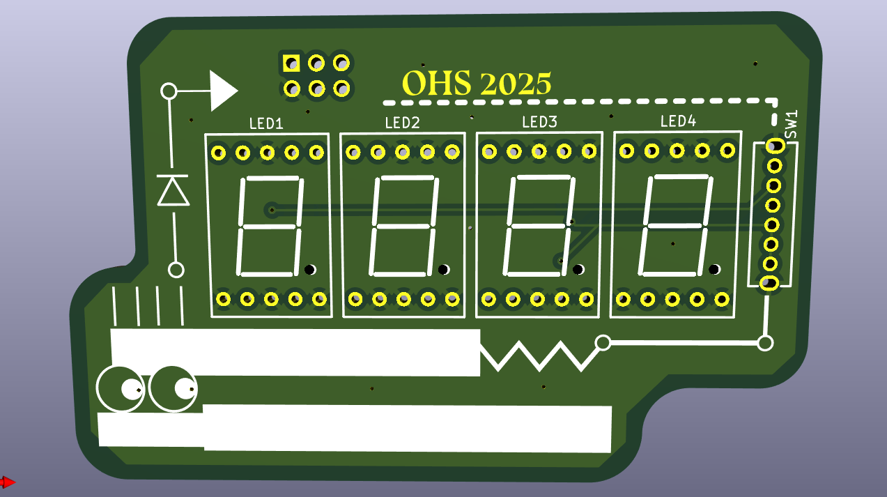
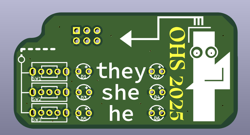
With cost a larger factor in mind, we simplified our designs, narrowing down to two: A simple printed "he" "she" "they" with LED indicators, and a 4 seven-segment displays that could be controlled to show "HE" "SHE" "THEY." We knew that simple LEDs would be fine being passively powered, but weren't sure about the seven-seg displays. Theoretically, they should just be LEDs underneath, but with datasheets referring to them being powered with AC, we wanted to be sure. So we ordered a handful from DigiKey and ran them under passive power for a few days with no ill effect, and decided to move forward. The designs we settled on for both aforementioned architectures are shown below. The seven-segment display uses a 3-throw switch to swap between the different pronouns, with each segment needed to display a pronoun connected with a diode to prevent backflow and a resistor to draw down the voltage to 2.1V, the point we found had the best power draw-brightness tradeoff.
End Product
Unfortunately, PCBA was going to be more expensive than expected, and the design was going to have to be simplified further. The final design that ended up being produced was a version of the simple LED one, where the switches were removed and instead LEDs could be manually inserted into slots to complete the circuit. A mount was added for a 3V battery, which could be substituted for the SAO header.
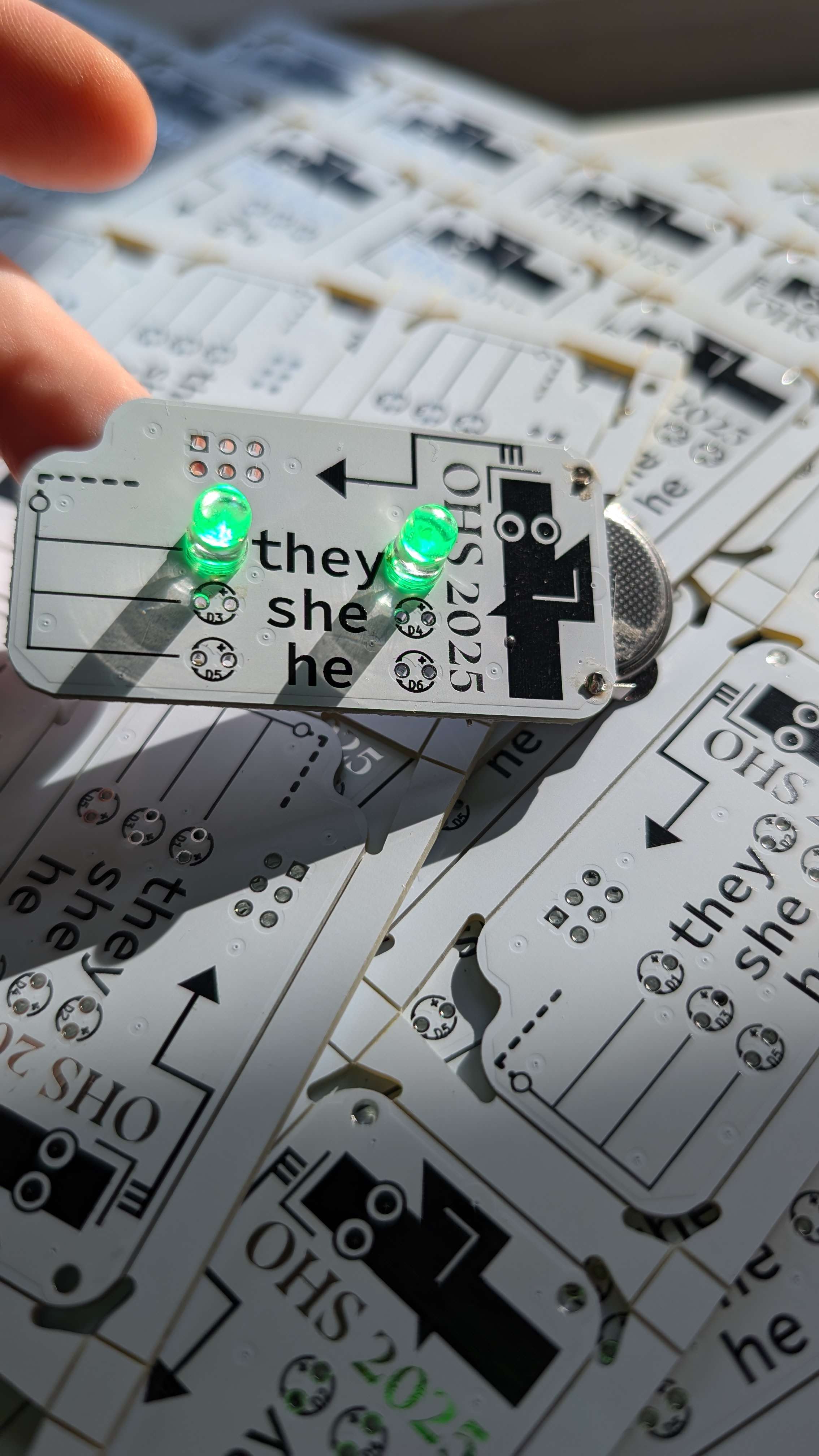
At some point down the line, I would like to get some of the seven-segment displays produced. They're really cute, and I think they're an elegant and visually interesting design.